During the week D drilled most of the remaining holes in the chassis – not a small job, which gets worse as your drill bit gets blunter and blunter. One of the reasons we had not yet put the floor on was that it would restrict access for drilling these holes. With them done, we could now consider putting the floor on.
Before placing the floor, we finished the top holes for the side panels. This just involved fitting the side panels, measuring and marking the holes, and then drilling. We have decided to only fold the side panels over the top, which means the pop rivets will be visible. Although this detracts slightly from how pretty the car will be, it also saves 258g. Using a conservative model, this is worth 0.08s at Zwartkops. I just made that up.

To make life easier, we again turned the chassis upside-down. Silicone sealant is used as a glue, to minimise vibration noise and to seal the panels. The chassis was thoroughly cleaned prior to applying it. The laser film was removed from the floor panels (main panel, as well as the small front one). The panels were then carefully placed on the chassis and the previously-drilled were holes lined up. Mainly for a cool photo we placed all the pop rivets, and then began the big job of making the attachment permanent. This is hard work with normal, manual, pop-rivet tools. D had a Stanley riveter, which is designed specifically to nip off the tips of your fingers as the rivet is popped. Mine was a Fragram one, which was marginally better.

We had not drilled the holes for the bottom of the side panel yet (i.e. there were no holes along the outside edges of the floor). It was now time to temporarily fit the side panels, and drill these holes. We did these one at a time, since it was useful to have the other side of the chassis open for access.

The panel was fitted over the floor (the previous fold did have to be opened slightly to make this easier). Several pop-rivets were inserted along the top edge (which was underneath) to ensure we had got the alignment right. G-clamps held it in place. Then we used ratched straps to keep pull the bottom in, tight against the chassis.
The positions were measured, and then holes were drilled through both the folded edge of the panel and the floor, into the chassis. We will leave these panels off as long as possible, to ensure good access to the chassis while we sort everything else out. At this point we declared that the long saga of the side panels is over. Well, sufficiently for now.
The chassis then got flipped back over, to finalise the fuel lines and brake lines. We placed the gearbox to roughly see whether it would clash with any of the lines, and unfortunately it became clear that there would be a problem with the top fuel line. We had to remove two of the p-clips and then bend the line again. In the process we almost pinched it (too tight a fold). Fortunately we managed to un-pinch it, and the line has not cracked. A couple of bends later and it’s looking good – possibly even more secure than the last time. Of course, research has shown that s-bends in your fuel line assist with cornering and straight-line stability.
The brake-line connections were then tightened, and the final p-clips attached. The only ones still to do are near the cylinders – we’ll hold off on those until the pedal box is correctly placed.

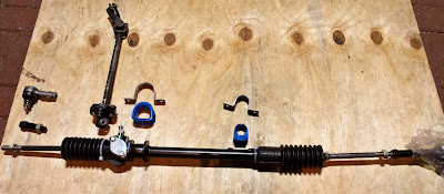
We also received our steering rack. We got it from Locost SA, although it’s been on order for several weeks. At one stage I tried to get a friend to bring one in from England. Unfortunately that plan was mucked about a bit by a volcano in Iceland, and some over-zealous health & safety officers. Looking at the size of it though (the rack, not the volcano), it might have strained the friendship a bit.
Placing the steering rack highlighted that the right front brake line may be in the way. Oh well, more rivets to be drilled out and moved.

Both front uprights have had their wheel-bearings fitted, although lessons were learnt while doing the first one. Needless to say the fit was extremely tight on this one, and the bearings had to be drifted on the whole way. The “Front Uprights” page has been updated, with lots of photos, to show how it’s done. It is a very messy job, but not too difficult.
In preparation for the assembly of the suspension, the drive-shafts have been assembled. These are those bits filled with bright-blue grease. They just needed a last bit of grease squeezed in, and then to be assembled. The gators (boots) have been held on with double cable-ties. Hopefully that is secure enough, and by doubling up there should be very little space for grease to get through.
A

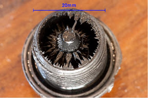
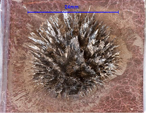
last job that I’ve been avoiding was cleaning and taking pictures of the diff magnetic filler plug. This has been soaking in paraffin for months. Finally I got round to doing it – there were quite a lot of metal filings attached. These were rinsed several times in paraffin, and then I took some pictures. I wasn’t able to attract all the filings from the plug onto another magnet, so I took a picture of what remained. Maybe this will be useful information at some stage.

Things start getting interesting now…
B

